 During the restructuring of the former Viareggio Hospital in Via Fratti, which has been turned into a National Health Facility, special attention was paid when selecting and designing the comfort and wellness systems, not only to achieve optimal thermo-hygrometric conditions but also to control the quality of the ambient air whilst minimising energy consumptions.
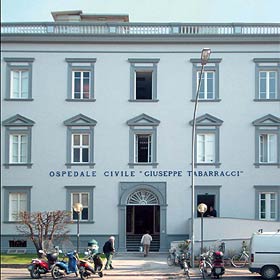
The restructuring of the former “Tabarracci” Hospital in Via Fratti, 530 Viareggio, was part of a building and facilities restructuring project with a change in destination of use to a National Health Facility. The interventions were to be performed without imposing interruptions on office operations and this has restricted the choice of equipment and the VRF heat recovery systems manufactured by Mitsubishi Electric.
Upon completion, primary air and exhaust stale air distribution and treatment systems were also installed.
This was a complex operation that was successfully completed thanks to the accurate planning of interventions and work stages.
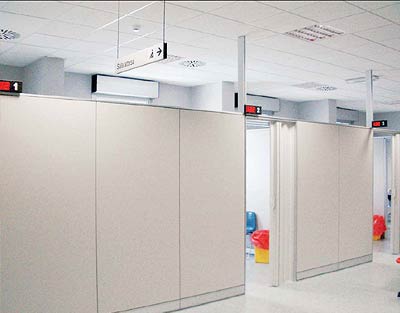
Second and third floors – cooling and heating system. Air diffusion by ducted internal units.
The main methodologies adopted and the most important HVAC systems installed are described below.
The building was already equipped with a number of traditional systems (hydronic) which included:
- a thermal power station.
- Cooling station comprising water coolers
- Air conditioning plant with a number of air handling units.
The restructuring project was prepared by the L.H.C. n. 12 Technical Department in Viareggio; the main project included the decommissioning of the existing systems and the realisation of new air conditioning systems, and the achievement of comfortable thermo-hygrometric conditions, control over ambient air quality and the minimising of energy consumptions.
These works were part of an energy policy implemented by the Local Health Centre n°12 in Viareggio aimed at saving on energy costs and achieving a rational and efficient use of energy.
The type of systems were carefully selected with these goals in mind from the wide range of solutions that modern technology currently has to offer. Following this analysis, it was decided to use Mitsubishi Electric direct expansion and variable cooling flow units:
- The existing and obsolete cooling station was decommissioned and replaced by a roof installed new type of thermal cooling station consisting of 12 outdoor units.
- The summer/winter conditioning system has 3 ducted units, 19 floor-mounted units and 123 wall-mounted units
- The ambient air recovery system uses 3 complete air handling units with a total capacity of 2,500 m3/h.
- An extremely simple and user-friendly thermo-hygrometric parameter management, control and monitoring system was also installed.
Due to the ultra-silent functions and compactness features, the Mitsubishi Electric units perfectly suited the aesthetic requirements of this building.
The ambient air recovery system uses 3 complete air handling units with a total capacity of 2,500 m3/h.
The restructuring interventions were programmed by the LHC n. 12 Technical Department and installed in phases as seen in the schedule below:
- 1997: Approval of the feasibility study
- 23.12.1999: Final Project approval
- 2001 : Executive Project approval
- 06.02.2002: Assigning of tender for works
- 07.10.2002: Handover of tendered works
- 15.10.2003: Activation of heating system with worksite open
- 21.04.2004: Completion of works
The particular type if system installed in the building made it possible to perform floor-by-floor restructuring with operational areas (worksites) restricted to work areas only. This meant that the areas not subject to restructuring activities were able to continue operating as usual and were available during the work schedule.
It should also be noted that during these works, the Health Centre in Via Garibaldi was moved to this same centre which caused a certain amount of interference with the work sites and operating zones.
Design Criteria
The plant systems were designed to ensure some basic conditions:
- safety and compliance with specific regulations
- reliability and maintenance over time of the investment value
- control flexibility
- environmental well-being
- containment of operating costs and energy consumption.
The main choices applied in order to meet these objectives are outlined below. Safety - The project choices were based on strict observance of all existing national and European regulations and standards.
The measures taken regarding fire risks were essentially:
- selection of self-extinguishing and flame retardant materials, with low toxic gas emissions when realising the distribution networks, insulation and cladding;
- selection of intrinsically safe equipment, which would not be the primary cause or propagator of fire;
- installation of all the equipment in outdoor technical areas or dedicated utility rooms, segregated by REI 120 partitioning elements from all other areas of the building;
- installation of fire dampers in ducts crossing the REI partitioning elements.
- Reliability and maintenance of the investment value over time
The objectives of high reliability and durability of the systems were pursued through the following interventions:
- a plant system supervision centre with preventive maintenance schedule;
- selection of standard equipment produced by firms with well-established presence on international markets, all providing efficient technical assistance services;
- engineering solutions and equipment of high quality and innovative technical content;
- suitable clearance area in the technical plants to ensure full access to the equipment, guaranteeing easy maintenance and in compliance with the instructions provided by the manufacturers of the various components;
- complete instrumental equipment to guarantee control over the functions of the plant systems and individual equipment, with appropriate connections to the centralised control centre;
- accurate descriptions using technical specifications, of the quality of materials and the methods of installation.
Description of interventions
- The plant systems which underwent intervention work were mainly the:
- Air conditioning systems
- Air ventilation and/or stale air exhaust systems
- Thermal regulation systems with field instruments and direct digital control regulating system designed for connection to a supervisory system.
The main plant facility works carried were completed at the same time, in accordance to the work schedule provided by the LHC n. 12 Technical Department in Viareggio:
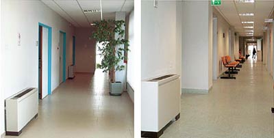
- first and mezzanine floor - cooling, heating, primary air distribution and stale air exhaust systems
- second and third floors – cooling and heating system.
- roof area - new thermo-refrigeration station.
- automatic control system
Description of the various systems
The basic elements taken into account when selecting the plant facilities proposed for the project were, in detail:
- The geometric configuration of the building (dual exposure to sunlight).
- The architectural restructuring project for the change in destination of use from Hospital to Local Health Centre (layout, foreseen work stations and utility spaces available).
- The need to install a new air handling system to guarantee constant exchange of outdoor fresh air to meet air exchange regulations.
- Modularity and user flexibility. Possibility to modify, in the future, the current modular layout without having to restructure the plant facilities.
- Need to achieve high energy-efficiency ratios with consequent savings on system running costs.
- Respect for the environment with low environmental impact plant proposals (the lowest atmospheric emissions obtainable using the currently available technology).
Type of new VRF systems - Our examination of the points above led us to opt for newly constructed VRF heat recovery plant systems comprising 12 outdoor units installed on the roof, each of which were connected by means of appropriate cooling circuits to a number of indoor units installed in the various offices.
A primary air renewal and stale air exhaust system was also installed.
The indoor VRF systems are able to provide or extract heat automatically, room by room; the renewed primary air is channelled to every room at a capacity foreseen by the applicable regulations. The VRF systems selected were built by Mitsubishi Electric.
As the outdoor units are fitted with inverters to control compressor capacity, it is possible, especially in the middle seasons, to cool areas which are subjected to the action of solar radiation and also heat areas, if necessary, on the other side of the building which is not exposed to direct sunlight with maximum energy savings. The flexibility of use is optimised as the supply of hot or cold air is proportional to actual needs. The outdoor units modulate system operations according to requirements. The cooling circuit distribution networks are made from small copper pipes, and the installation led to an appreciably fast execution of works.
The ducted air flow system captures stale air in the climatised environments and, before exhausting it outdoors, it recovers the thermo-hygrometric content via special enthalpic recovery units.
As the VRF systems do not interact in any manner with the existing cooling and heating plant system, they proved to be the only solution that would allow the possibility of performing contemporarily:
- the floor redevelopment project
- installation of the new thermal cooling system on the roof.
- functionality of the offices during the work-in-progress stages.
Primary air treatment and expulsion systems - The primary air handling system comprises 3 indoor units, each fitted with a fresh air delivery fan, a stale air recovery fan, a filter system, Lossnay enthalpy type heat exchanger, a by-pass damper, permeable film humidifiers and a direct expansion fan coil.
Mitsubishi Electric has designed a special enthalpy heat recovery unit which is able to recover the sensitive and latent heat content in stale air exhausted from environments and then expel it outdoors.
This recovery unit called a “Lossnay element” is cross flow plate type fitted with an exchanger diaphragm made from specially treated paper. The exceptional properties of thermal exchange and the permeable features of this special paper against humidity, guarantees maximum exchange of heat and humidity via the two air flow streams that are blown through the recovery element. The final result is a ventilation system with decidedly outstanding features that guarantee maximum levels of health and comfort in handled environments, which also lead to substantial energy savings.
The above generates a decrease in running costs implicated by the delivery of fresh air into the environment during the cooling phase in summer and the heating phase in winter.
The simple and indestructible features of this structure guarantees long life expectancy with no maintenance costs.
Dust and solid particles can only accumulate on its surface and can be removed using a standard vacuum cleaner.
The features of its surfaces, which prevent the proliferation of bacteria and are not prone to blocking, can guarantee maximum long-life during operating functions.
Dust removal - A high-efficiency filter installed on the air handling unit is able to function without maintenance for a maximum of 3,000 hours, with a 65% colorimetric performance.
Automatic free cooling - When the air conditioning system is operating in cooling mode and the outdoor temperature has a value below room temperature (as typically occurs during summer nights), the primary air handling unit will detect this situation and automatically cut-off the air flow recovery element. Direct emission into the environment of outdoor air which is colder than the ambient temperature helps to reduce the cooling load that the system is subjected to. Humidification - the innovative permeable film humidification system that runs on a natural process of evaporation is most interesting. The efficiency of humidity emitted into the air has increased considerably, hence reducing the resistance of used materials. The use of a three-layer film made it possible to obtain the exact necessary transfer of moisture without any diffusion of limescale dust, as is the case when using ultrasonic humidifiers. Ensuring the right level of moisture in any environment creates maximum comfort environments, preventing unpleasant conditions such as those resulting from dry eyes and throat, which typically occur when there is insufficient levels of moisture in the environment. The evaporation surface is roughly 8.5 times that of large sized natural evaporation humidifiers, and its performance is 6 times higher.
The optimisation of the air stream trajectories inside the unit and water injection techniques that have been adopted, has made it possible to increase the efficiency of the humidification process even further. The system also controls the level of humidity in stale air being expelled, guaranteeing running operations that best safeguard the outdoor environment characteristics.
This solution eliminates all diffusion of impurities, such as limescale and siliceous dusts from the environment. The air delivered to the environment is therefore purer and less dusty. The setup of the outdoor air handling unit together with the supervision and control system allows users to manage all the controlled parameters (temperature, humidity, indoor air purifying and limitation of noise) with maximum energy savings.
As regards the conditions for the maintenance of the air ducts, they have been structured to allow access from the top of each straight section, or with accessible hatch doors or the disassembly of the curves, all flanged, through the suspended ceiling which is accessible in order to conduct cleaning operations.
Condensate exhaust networks - All indoor units are connected to a high density polyethylene condensation exhaust network. At the foot of each column, and the connections to the various floors, there is an inspection hatch and a sling to aid cleaning interventions on the network.
The connection to the general exhaust network was achieved by installing "constantly wet" siphons.
The exhaust columns are open at the top with an outlet into the atmosphere, to avoid, along with the constantly wet siphons, the possibility of unpleasant odours being channelled into the building.
All networks are equipped with horizontal sub-trims, straps, siphons and inspections at curves and junctions that require it.
Inspections have been planned for the straight sections, one every 15 meters at most, or at least in sufficient numbers to ensure the cleanliness of the networks in case of accidental occlusion.
Controller and management systems
An integrated controller system is foreseen, consisting of a family of hardware and software modules that together constitute an integrated system of controllers, sensors, actuators, and operator interface devices. These systems allow the supervision, control and management of technological facilities for conditioning, ventilation and heating.
The systems have the ability to integrate various functions necessary to manage the building, thus simplifying the job of operators to ensure comfort. Control points are provided for each level (concentration) for the management of the environment unit of VRF systems. Each unit operates independently, performing on their own specific controls and alarm management. The failure of a single component or a connection on the network does not stop execution of the functions of control over other equipment.
The supervision system allows, in short, the management of controlled parameters (temperature, time etc..) Manned by a local or remote operation from any location (personal computer) of any operator, after entering a password The interface between the operator and supervised facilities is therefore a personal computer that allows the control functions, alarm management, control and analysis of the network and data processing.
The software provided minimis the operator instruction phase thanks to the interactive menu and the use of standard PC software applications. The user interface requires the use of a mouse and pointer selection menus, this simplifies learning requirements and makes the management programme user-friendly for all operators.
The user is therefore in a position to send commands to the users or modify a set-point tracking using a mouse on a graphic page.
Varying levels of access are provided to limit the operation of workstations and manipulation of basic data on the basis of the responsibility of each operator. The system is modular in nature and allows the expansion, with the simple addition of hardware and software applications such as workstations, field controllers, sensors, actuators, etc...
Download
Case History
Download the complete Case History
Download