An unexpected reality of the twenty-first century, built in just as unlikely a place.
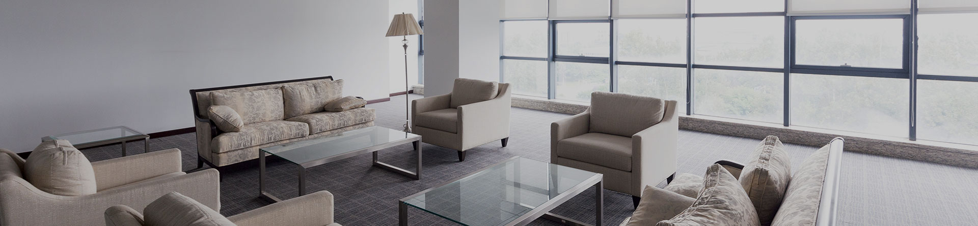
 This is the new Tiscali Campus, created from nothing in Sa Illetta, a lagoon area just outside Cagliari, which comprises a complex of office and server buildings, providing cutting-edge architectural and installation choices.
The Tiscali Campus was designed by Studio Aldo Rossi Associati in Milan and consists of a complex of four 3-storey rectangular buildings, covered in red trachyte and Orosei marble, and hosts all the Group activities. The total area dedicated to office space is approximately 16,000 square metres and, so far, the company has employed 800 people.
The facade of the main entrance side of the building, plays with bands of black basalt and white limestone and recalls the Pisan-Romanesque style of Sardinian basilicas. But it also blends well with the modern bar code and the binary computing systems.
The campus also has some satellite sections with a campidanese house with a bar, restaurant and nursery for employees' children, and the building that houses the servers and computers for the processing of data traffic, which can be summarised in one single number: 50 million e-mails a day. The entire complex is located within an immense park dotted with olive trees and fountains. The office buildings are all equipped with sophisticated HVAC Mitsubishi Electric systems, using the variable refrigerant flow (VRF) types, based on a highly original project designed by Professor Eng. Carlo Bernardini from Cagliari.
The HVAC system installed in the Campus offices has the task of maintaining the temperature and relative humidity indicated in the ASHRAE project for such applications, plus adequate ventilation to ensure high level of hygiene in the environments, combined with an even distribution of air avoiding the formation of currents. The double exposure of the buildings also required a highly evolved zone control system, along with the installation management system.
With a complex of this magnitude, it goes without saying that the energy aspect and environmental impact were of fundamental importance when choosing the type of installation systems and the HVAC equipment.
Why choose VRF
Among the many alternatives considered during the design and engineering phase, the final choice fell on the use of VRF heat pump systems, with variable cooling capacities, produced by Mitsubishi Electric and comprising PUHY YMF-250-C outdoor units and ducted PEFY-VMMA-A indoor units, for a total of 55 outdoor units and 287 indoor units.
The treatment of outdoor ventilation air and energy recovery have been obtained using appropriate total, air-to-air cross-flow heat recovery units, again produced by Mitsubishi Electric, more specifically the Lossnay LU-500 model.
The VRF systems designed for the Campus buildings have a number of important positive features:
High environmental value. In fact, the operating efficiency level of the installations is very high and expresses high COP values in all load conditions, particularly during partial capacity periods, which occur most of the year. This generates TEWI values (equivalent total impact on global warming) which are fairly immaterial and much lower than those of traditional systems. In addition, thanks to the high COP values, the operating costs for energy use are particular convenient in relation to the immensity of the works, and much less than the typical values of traditional systems.
Excellent comfort management. The Mitsubishi Electric G-50 centralised controller is a highly sophisticated instrument used to control comfort levels and offers a variety of top quality management functions. The remote controls of the Mitsubishi Electric PARF 27 MEA indoor units all report to this central system (the technical specifications for all these systems is provided later on).
Vast energy recovery capacity between exhausted air and supplied air flows, which increase system efficiency and enhance their environmental value. This function is performed, as stated above, by the Lossnay LU-500 total heat recovery unit.
Easy installation of the systems within the buildings. In this case, a special mention should be given to the originality of the system solution designed by the engineering and design team, as described below. In short, the Mitsubishi Electric VRF systems with ducted indoor units require minimum space above the suspended ceilings and also generate savings in construction work.
Super quiet operations. The indoor and outdoor units have intrinsic low noise operation features. In the environments, this low noise is abated even further by means of insulated flexible ducts installed between the indoor unit and the air diffusers.
Modularity of the system and therefore no stoppage caused by accidental incidents, one of the risks that centralised units are subjected to. Well-defined sizes of both indoor and outdoor units were chosen in order to ensure that, in case of failure, the unit can be quickly repaired or parts replaced using models in stock.
No need for utility rooms in the areas used. The Mitsubishi Electric VRF variable refrigerant flow systems do not require utility rooms, to the benefit of the total exploitation of space.
This combination of advantages and characteristics confirmed the choice of variable refrigerant flow systems (VRF) for the buildings intended for office activities at the Tiscali Campus.
Project Outline
The design team, coordinated by Prof. Eng. Carlo Bernardini comprises engineers Luigi Berti, Enrico Berti, Pier Luigi Schintu, Carlo Foddis and the surveyor Francesco Cossu, addressed the layout of the plant conducting an in-depth analysis of the specific characteristics of the buildings. Each building has a rectangular layout and consists of two large symmetrical open space areas, separated in the middle by service areas including stairs, wash rooms etc.; the presence of similar service areas is also repeated on the two areas at the ends of these buildings.
The climatisation of the open spaces destined for office use was addressed with the installation of two parallel rows along the length of the offices, of PEFY-VMMA-A, ducted indoor units; a typical space area includes a total of 10 units (5+5), each connected by circular flexible ducts with 6 diffusers installed flush with the suspended ceiling. The air flow capacity handled by each internal area is 750 m3/h, distributed by the six diffusers, each with a 125 m3/h capacity. The diffusers themselves produce two continuous parallel lines in the suspended ceiling, the air flow is delivered towards the interior space by both rows of diffusers. The air distribution layout on a typical building floor is shown in the diagram. These units only operate by air circulation. The suspended ceiling does not cover the entire width of the building, but leaves space along the perimeter walls for the installation of air grilles which suction the exhausted air that is then ducted to the heat exchanger.
The ducting of air from the outside is achieved by means of a double row of floor nozzles installed on the mezzanine floor along the perimeter walls. This also creates air blades that contrast the return of hot summer air and heat loss in winter, according to temperature differences, and also prevents the formation of cold drafts.
The outside air blown through the floor is collected up by induction from the indoor units and redistributed in a mixture to the interior areas. The suction of exhausted exhaust air is performed by grilles installed high up in the areas without suspended ceilings.
The solution developed in this manner has at least four advantages:
Uniform thermo-hygrometric treatment of the entire environment, plus it offers maximum freedom to control the 2 + 2 opposite zones independently, thanks to the flexibility of the VRF system.
Diffusion of outside air with air knives that perform the dual function of indoor air ventilation whilst preventing hot air from entering or heat loss, depending on the season.
The impeccable design of the suspended ceiling with the two rows of continuous linear diffusers that run along the entire length.
Uniform air distribution, with no currents or stagnation areas.
The areas at the two ends of the buildings are also treated using ducted indoor units and linear diffusers; in this case the row of diffusers face the glass wall at one end and is therefore perpendicular to the rows in the interior spaces, as can be seen in the diagram.
Finally, the installation of the outdoor units was performed on the roofs of the buildings and the units themselves were concealed behind or inside appropriate structures and utility rooms that characterise the construction work, as can be seen in the diagrams. This means that no equipment is visible from the outside and do not alter the building lines in any manner at all.
The technology of the installed VRF systems
The Mitsubishi Electric VRF heat pump installed in the Campus Tiscali represents the state of the art regarding the production of high efficiency heating/cooling energy with minimal environmental impact. These systems are modular and therefore the description of their technological characteristics below refers to typical indoor and outdoor units.
Outdoor units
The reference model is the PUHY YMF-250-C for outdoor installation; this unit can be connected to up to 16 indoor units, maintaining full capacity cooling or heat pump heating operations with a 2-pipe connection circuit. The main components of the machine include a scroll compressor equipped with a linear controlled Inverter, with operating frequencies that range from 20 to 105 Hz and allows continuous adjustment of the heating or cooling output capacity from 16% to 100% of nominal values. It also has a fan coil serving the package type heat exchanger fan coil with copper tubes and aluminium fins. It also has a 4-way blow valve to allow reverse cycles, allowing the transition from cooling to heat pump heating; it also defrosts the outdoor fan coil using the heat pump, when needed. Other features of the machine consist of an oil separator, solenoid valves, liquid refrigerant receiver, accumulator on the line where the gas is suctioned to the compressor, refrigerant filter drier, high and low pressure sensors, safety pressure switches and bypass valves. There is also a complete electrical and control panel. The refrigerant used is R-407C, a HFC harmless to the ozone layer.
Indoor units
For indoor units, the reference model is the PEFY-VMM-A type for concealed installation above suspended ceilings; it basically comprises a direct expansion 2-row refrigerant-air cross-fin heat exchanger, fitted with an electronic expansion valve for continuous monitoring of the refrigerant from 25% to 100%. There is also a Sirocco type fan coupled directly to a 2-speed single-phase induction electric motor; the prevalence of the fan is able to channel the air that feeds the diffusers. A synthetic fibre filter regenerated by washing or dry-cleaning is provided with the machine. The unit is suitably insulated to prevent condensation from forming on the walls. A drain pan with a suitable exhaust port, collects the condensation that forms during the cooling and dehumidifying of the treated air. The cooling circuit connections are all easily accessed.
Lossnay units for Large Capacity Installations (model LU 500 modules - 5,000 m3/h)
The reference fresh air exchange model is the LU 500 type and consists of a total heat-exchange recovery unit and an enclosure housing.
The passageways used for incoming air and exhaust air are physically separated to prevent unwanted mixing of the two air streams. The exchange pack assembled with exchange diaphragms and corrugated separators made of specially treated paper, has a high thermal conductivity level (equivalent to that of aluminium and copper) are able to exchange both sensible and latent heat. The exchange diaphragms, permeable to latent heat, create a barrier against the summer humidity and vice-versa against the dry climate in winter; the total heat exchange allows outdoor air to reach thermo-hygrometric levels which are close to those of the ambient, this achieves a 70% reduction on the air renewal heating load.
Lossnay units for large plant systems are an exclusive Mitsubishi Electric product, with 11 machines installed with a capacity of 5,000 m3/h each.
Centralised system controller G-50
The Mitsubishi Electric G-50 centralised system controller allows for quick and intuitive management of all air conditioning systems on the Tiscali Campus, using a single device which comprises a keypad and an alphanumeric LCD monitor, connected to the air conditioning units by means of a dedicated line consisting of a non-polarised two-wire cable. The G-50 system can control up to 50 air conditioning systems independently and collectively. It allows for direct integration without the need for additional dedicated hardware, using a LAN Ethernet type network with other centralised controls and dedicated monitoring systems. It displays the representation of data via the alphanumeric display and uses the control keypad to manage all operations. It is possible to conduct basic programming and system configuration, with non-volatile data memory bank. It has a historical archive that records all anomalies and malfunctions. It is also possible to handle digital inputs and outputs for collective information on the operational status of air conditioning units, the switching on and off by outdoor devices plus the emergency stop system. It includes a time scheduler which works on a weekly basis with different programmes and a series of daily sub-programmes to control the main air conditioning regulating principles, further to the disabling/enabling of the main remote control principles. It provides automatic notification of failures by sending e-mail to 5 different addresses with at least the code and description of the anomaly. Many other functions are also available.
Meanwhile, it should be noted that a new version of this system is now available, called G-50A, whose capacity and features are even more advanced.
To interact with the air conditioning system, simply connect the G-50A system controller installed on the equipment to the same corporate Ethernet LAN network, from any PC, not necessarily dedicated to the same; all that is needed then is to install the Internet Explorer software.
Once started, simple enter your password to access the various functions of the G-50A system controller, after which a screen appears that displays all the air conditioners connected to the circuit in the form of icons.
Like a website, you can then navigate through the system, moving your mouse over the icons of the individual air conditioners, read their name and operational status. Then, by selecting a different view type, you can check the various parameters such as ambient temperature, set temperature and so on.
This means it is possible to change the different settings, control the air-conditioner regime etc.. The G-50A system provide complete control of the plant system, whereby the fact that it is easy to examine, adjust and control is highly appreciated among users. The system also has a weekly timer and a yearly calendar which can be used to plan customised and automatic operations, such as during the holidays, summer closures etc..
Remote control for PAR 27 F MEA indoor units
This wall mounting device provides control over each indoor unit and selection of their operating mode. It is equipped with a temperature control microprocessor, an alphanumeric display, fan speed switches, 24 hour timer, self-diagnosis function that reports any abnormalities detected in the outdoor units, the indoor units and other remote controls distributed throughout the system, including the centralised controller. The device is interfaced with the indoor unit and the rest of the system via a transmission bus consisting of a non-polarised twisted pair. It can control group operations up to a maximum of 16 indoor units.
Conclusions
The HVAC systems installed at the new Tiscali Campus are the most advanced indoor air-conditioning systems currently available with actual sustainability and environmental safeguarding characteristics.
The operating results collected to date, and the level of comfort for people which was reported during this initial period of operations, confirm the compliance of the Mitsubishi Electric VRF systems under all operating conditions that occurred, achieving complete user satisfaction.
The system consists of 55 outdoor units connected to 287 indoor units, which all use the ecological refrigerant R-407C. In addition there are also 11 total heat exchangers for pre-treating of the outdoor ventilation air and the recovery of the air before being exhausted.
Download
Case History
Download the complete Case History
Download